FALL DETECTION SENSOR
June 2021
Background
As part of the Medical Electrical Engineering lab course, my group and I developed a fully analog and a digital-analog fall detection sensor using LTspice for designing the circuit and simulating the outcome.
A motivating fact was that almost one-third of old people beyond the age of 65 tumbles at least once a year. Also elderly people are usually living alone or in assisted housing and it can happen that their falls are going unnoticed for quite some time. To provide help as quickly as possible fall sensors with an integrated emergency call assistant are increasingly used in the domestic and supervised setting.
If there is a fall, it can be recognized using an accelerometer by two criteria. The free fall and the collision with the ground have to be identified. By means of a microcontroller other people can be informed by switching on a LED in another room or making a sound.
Going into greater detail, we developed two different circuits, one completely analog circuit without any microcontroller and one using an Arduino UNO and analog-to-digital conversion.
The Analog Circuit
The completely analog circuit is focusing on the free fall and is done with several potentiometers, an adder, an one-shot multivibrator and four comparators, self-constructed with basic electronic components. The first three comparators compare the analog measured sensor signals of the three axes with the given voltage levels from the data sheet of the accelerometer, set by the potentiometers. Output signals are generated based on this comparison. The adder and the fourth comparator are used to check the success of all comparisons and to transmit the output to the one-shot multivibrator. The astable state of the multivibrator is triggered by the impulse of the short moment of the free fall, converting a short into a long signal. Instead of an emergency call this last output signal can be connected to a buzzer or an LED and catch other people's attention.
What was used in the circuit:
Components | Number |
1 kOhm Resistor | 23 |
1.5 kOhm Resistor | 6 |
10 kOhm Resistor | 4 |
1000 kOhm Resistor | 1 |
Transistor BC547B | 2 |
Operational Amplifier LMC6482 | 13 |
100 nF Capacitor | 1 |
100 μF Capacitor | 1 |
Diode 1N4148 | 1 |
5V Voltage Regulator 79L05 | 1 |
5V Voltage Regulator 78L05 | 1 |
12V Supply Voltage | 1 |
Rotary Potentiometer | 8 |
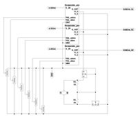
The circuit was implemented as shown below:
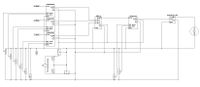
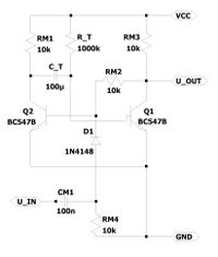
The circuit is using a monovibrator, a comparator, and an adder shown here.
The Analog-Digital Circuit
The analog-digital circuit is based on the first circuit. The first three comparators and multiple potentiometers do exactly the same, but the three output signals of the comparators are connected with three inputs of the Arduino. The analysis of these signals is done by implemented algorithms.
What was used in the circuit:
Components | Number |
Rotary Potentiometer | 6 |
1 kOhm Resistor | 23 |
Arduino UNO | 1 |
Operational Amplifier LMC6482 | 12 |
5V Voltage Regulator 79L05 | 1 |
5V Voltage Regulator 78L05 | 1 |
Miniature Buzzer 2-4V | 1 |
12V Supply Voltage | 1 |
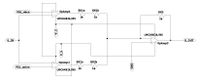
The circuit was implemented as shown below.
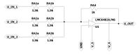
Using the following comparator.
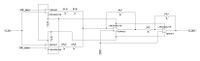
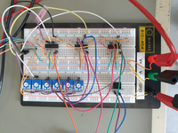
The implemented circuit looks like this:
The Result
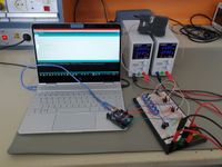
In the following video, you can see how the fall detection sensor works and hear the alarm. (Make sure to turn on your sound!)
For more details feel free to ask for the full report.